Welcome to ISOWIND
![]()
Operating Temperature for Insulation Panel Thicknesses |
|||||||||||||||
External Ambient |
Operating Temperature (°C) |
||||||||||||||
25 |
20 |
15 |
10 |
5 |
0 |
-5 |
-10 |
-20 |
-25 |
-30 |
-35 |
-40 |
-45 |
-50 |
|
60mm |
|||||||||||||||
100mm |
|||||||||||||||
130mm |
|||||||||||||||
150mm |
|||||||||||||||
Panel(s) should be selected to achieve a maximum thermal transmittance of 10W/sq.m |
|||||||||||||||
Per-calculated cold room int.: 2000mm height |
||||||||||||||
A |
B |
C |
D |
E |
F |
G |
H |
L |
M |
N |
P |
R |
||
CM |
120 |
160 |
200 |
240 |
280 |
320 |
360 |
400 |
440 |
480 |
520 |
560 |
600 |
|
1 |
120 |
|||||||||||||
2 |
160 |
3.8 |
H200 |
|||||||||||
3 |
200 |
4.8 |
6.4 |
8.0 |
||||||||||
4 |
240 |
5.8 |
7.7 |
9.6 |
11.5 |
|||||||||
5 |
280 |
6.7 |
9.0 |
11.2 |
13.4 |
15.7 |
||||||||
6 |
320 |
7.7 |
10.2 |
12.8 |
15.4 |
17.9 |
20.5 |
|||||||
7 |
360 |
8.6 |
11.5 |
14.4 |
17.3 |
20.2 |
23.0 |
25.9 |
||||||
8 |
400 |
9.6 |
12.8 |
16.0 |
19.2 |
22.4 |
25.6 |
28.8 |
32.0 |
|||||
9 |
440 |
10.6 |
14.1 |
17.6 |
21.1 |
24.6 |
28.2 |
31.7 |
35.2 |
38.7 |
||||
10 |
480 |
11.5 |
15.4 |
19.2 |
23.0 |
26.9 |
30.7 |
34.6 |
38.4 |
42.2 |
46.1 |
|||
11 |
520 |
12.5 |
16.6 |
20.8 |
25.0 |
29.1 |
33.3 |
37.4 |
41.6 |
45.8 |
49.9 |
54.1 |
||
12 |
560 |
13.4 |
17.9 |
22.4 |
26.9 |
31.4 |
35.8 |
40.3 |
44.8 |
49.2 |
53.8 |
58.2 |
62.7 |
|
13 |
600 |
14.4 |
19.2 |
24.0 |
28.8 |
33.6 |
38.4 |
43.2 |
48.0 |
52.8 |
57.6 |
62.4 |
67.2 |
72.0 |
Per-calculated cold room int.: 2000mm height |
||||||||||||||
A |
B |
C |
D |
E |
F |
G |
H |
L |
M |
N |
P |
R |
||
CM |
120 |
160 |
200 |
240 |
280 |
320 |
360 |
400 |
440 |
480 |
520 |
560 |
600 |
|
1 |
120 |
|||||||||||||
2 |
160 |
4.6 |
H200 |
|||||||||||
3 |
200 |
5.8 |
7.7 |
9.6 |
||||||||||
4 |
240 |
6.9 |
9.2 |
11.5 |
13.8 |
|||||||||
5 |
280 |
8.1 |
10.8 |
13.4 |
16.1 |
18.8 |
||||||||
6 |
320 |
9.2 |
12.3 |
15.4 |
18.4 |
21.5 |
24.6 |
|||||||
7 |
360 |
10.4 |
13.8 |
17.3 |
20.7 |
24.2 |
27.6 |
31.1 |
||||||
8 |
400 |
11.5 |
15.4 |
19.2 |
23.0 |
26.9 |
30.7 |
34.6 |
38.4 |
|||||
9 |
440 |
12.7 |
16.9 |
21.1 |
25.3 |
29.6 |
33.8 |
38.0 |
42.2 |
46.5 |
||||
10 |
480 |
13.8 |
18.4 |
23.0 |
27.6 |
32.3 |
36.9 |
41.5 |
46.1 |
50.7 |
55.3 |
|||
11 |
520 |
15.0 |
20.0 |
25.0 |
30.0 |
34.9 |
40.0 |
45.0 |
49.9 |
54.9 |
59.9 |
64.9 |
||
12 |
560 |
16.1 |
21.5 |
26.9 |
32.3 |
37.6 |
43.0 |
48.4 |
53.8 |
59.1 |
64.5 |
69.9 |
75.3 |
|
13 |
600 |
17.3 |
23.0 |
28.8 |
34.6 |
40.3 |
46.1 |
51.8 |
57.6 |
63.4 |
69.1 |
74.9 |
80.6 |
86.4 |
The indicated measurements are net internal dimension in cm; to obtain external measurements add:
S/6+12 cm S/9+18 cm S/13+26 cm
To obtain the external heights add:
with floor: S/6+12 cm S/9+18 cm S/13+26 cm
without floor: S/6+6 cm S/9+9 cm S/13+13 cm
| ECCENTRIC LOCK |
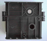
| Eccentric lock is custom designed and manufactured to our specification. It is made from high impact ABS plastic with rust resistant GI steel. During the foamed-in-place process, the locks are embedded every 800 mm for the wall panels and every 400 mm for ceiling and floor panels. During the installation, an Allen Key is used to latch the male and female eccentric locks together. The locking action is in two steps. Firstly to latch the locks together and secondly is pulling the panels together to form a tight seal, preventing cold air to escape from the cold room. After the latching process a flush PVC cap is used to close the hexagon key access hole. |
| COVED CORNER |
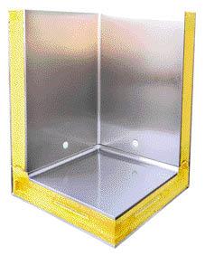
Corner panels are joined together using single place. ISOWIND coved corner comes in different dimensions to cover different panel thickness. |
PANEL JOINT SEALS |
|


 Camlock
 Coved_corner